Documentation
Design Overview
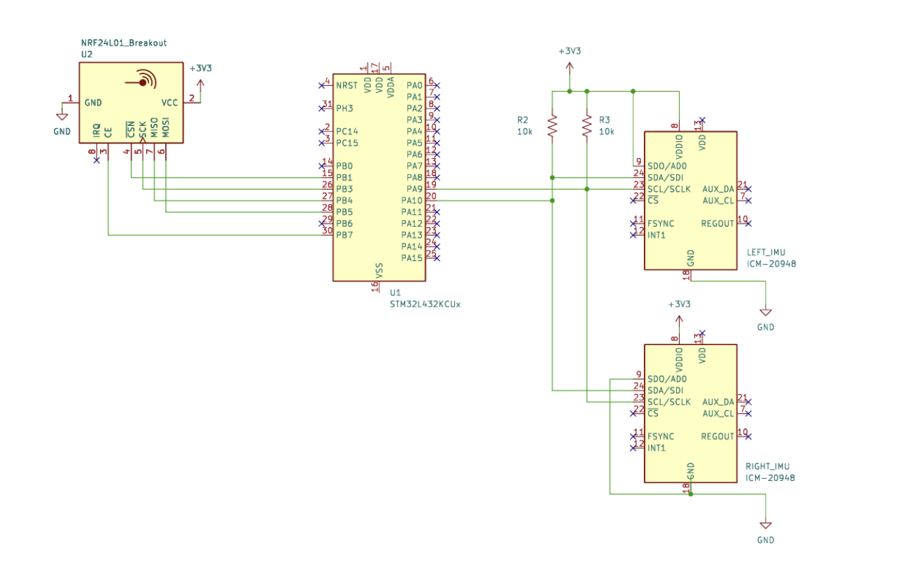
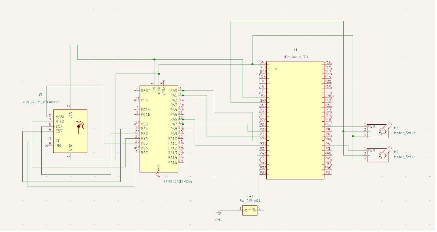
Two Adafruit TDK InvenSense ICM-20948 9-DoF IMUs attach onto the user’s arms to measure pitch angle. The IMU signals communicate to a first MCU through an I2C interface. The MCU takes in the IMU sensor data and uses this information to decide what the motors will do (outputting motor states) to a second MCU, then to an FPGA to drive the servo motors.
Two NRF24L01 Wireless Communication Receiving modules send signals between the two MCUs. This allows us to eliminate wires between the Remy headpiece and the other components, reducing restriction on users’ movements.
The FPGA takes input from the MCU with 4 pins such that there are 16 possible states for the motors/rat, with the first two bits representing states for the left motor and the last two bits representing the states for the right motor. The FPGA drives the servo motor using PWM signal which controls the rat arm movements.
The figures below display the circuit schematics for this project.


For all code used in this project, visit our Remy the Rat organization on GitHub.
New MCU Features
In order to reduce the number of wires and thereby improve the wearability and user experience of the design, the I2C communication protocol was chosen to communicate between the IMU sensors and the microcontroller. The I2C peripheral was a feature of the microcontroller that was not explored during the E155 labs.
In order to implement this protocol, drivers were written from scratch that implemented I2C peripheral configuration, I2C reading, and I2C writing. For more information on implementation, refer to the MCU page.
New FPGA Features
The FPGA is in charge of generating PWM signals to drive the servo motors that move Remy’s arms. The FPGA takes in the states from the second MCU through 4 GPIO pins and drives PWM signals to the motors to move them to a distinct state. The 2 Most Significant Bits of the state variable drive the left motor, while the 2 Least Significant Bits drive the right motor. Thus, each motor has 4 distinct states. For more information, see the FPGA page.
Bill of Materials and Budget
| Item | Part Number | Amount | Unit Price | Total |
|---|---|---|---|---|
| Adafruit TDK InvenSense 9-DoF IMU | ICM-20948 | 2 | 14.95 | 29.90 |
| Servo Motors | SG51R | 2 | 5.95 | 11.90 |
| RF Module | NRF24L01 | 2 | 1.96 | 3.92 |
| Chef’s Coat | B00O7PBRJW | 1 | 13.56 | 13.56 |
So, the total price of this project was $59.28, but the chef coat was just for fun, so the core pieces of this project were well under $50, which is well under budget.