MCU Design Details
General Overview
This project uses two MCUs to handle both the reading of IMU data and the transmission of state information. The first MCU on the chef jacket reads acceleration and gyroscope data from the 2 IMUs mounted on the user’s arms through I2C. It also processes the data to then extrapolate state information for the arm movements. Lastly, this IMU writes state data through SPI to the first RF module to then transmit to the second RF module.
The second MCU reads data from the second RF module to receive state information for the movement of the arms. This MCU then sends the state information to the FPGA through GPIO.
- Input
- Receives signals from the IMU via I2C: a new feature for processing IMU signals.
- Processing
- Processes IMU data (also new!) to:
- Determine motor actions.
- Decide the state to be transmitted.
- Output
- Sends signals or states to the RF chip via SPI. (also new!!)
IMU Integration
In order to communicate with IMU sensors, I2C was chosen. This protocol reduces the number of wires used to connect between the chips and the MCU. There were three functions written for the I2C peripheral driver: one for configuration, writing to a chip, and reading from a chip. Writing and reading were implemented as follows:
- Writing
- Set address
- If stop flag is set, configure autoend mode (will send stop signal automatically after the number of bytes sent equals the data package size)
- Set data package size
- Set read/not write bit to 0
- Set start signal
- For each byte in the data package size:
- Wait until transmit buffer is empty or the TXIS flag is set
- Write data to TXDR buffer
- Reading
- Set address
- Set autoend mode (will send stop signal automatically after the number of bytes received equals the data package size)
- Set data package size
- Set read/not write bit to 1
- Set start signal
- For each byte in the data package size:
- Wait until the receive buffer has data in it or the RXNE flag is set
- Save data from RXDR buffer
For configuration of the I2C peripheral, it was important to correctly configure timing of the clocks going into the peripheral. The system clock was configured at 64 MHz and a prescaler of eight was used to slow down the clock going into the peripheral to 8 MHz. The I2C peripheral was configured to run at 400 kHz Fast Mode from this speed based on Table 181 from the STM32 Reference Manual. The speed of 400 was chosen as it is the maximum speed an ICM20948 chip can run I2C communication with.
A driver was also written for the ICM20948 chip based off of the I2C driver. The chip was configured by resetting the chip, clearing sleep mode, and enabling the accelerometer and gyroscope or by sending the signals {0x06, 0x02, 0x00} through I2C to the corresponding address of the chip. Additionally, a function was written to configure the accelerometer and gyroscope readings. The sample rate divisor for both sets of readings was set to zero by writing 0x00 to the location 0x10 and to the location 0x00. The digital low pass filter onboard the ICM chip was enabled and configuration six was chosen for both sets of readings by writing to location 0x14 for the accelerometer and 0x01 for the gyroscope. Finally, in order to read gyroscope and accelerometer data, twelve bytes of data were read starting from the address 0x2D.
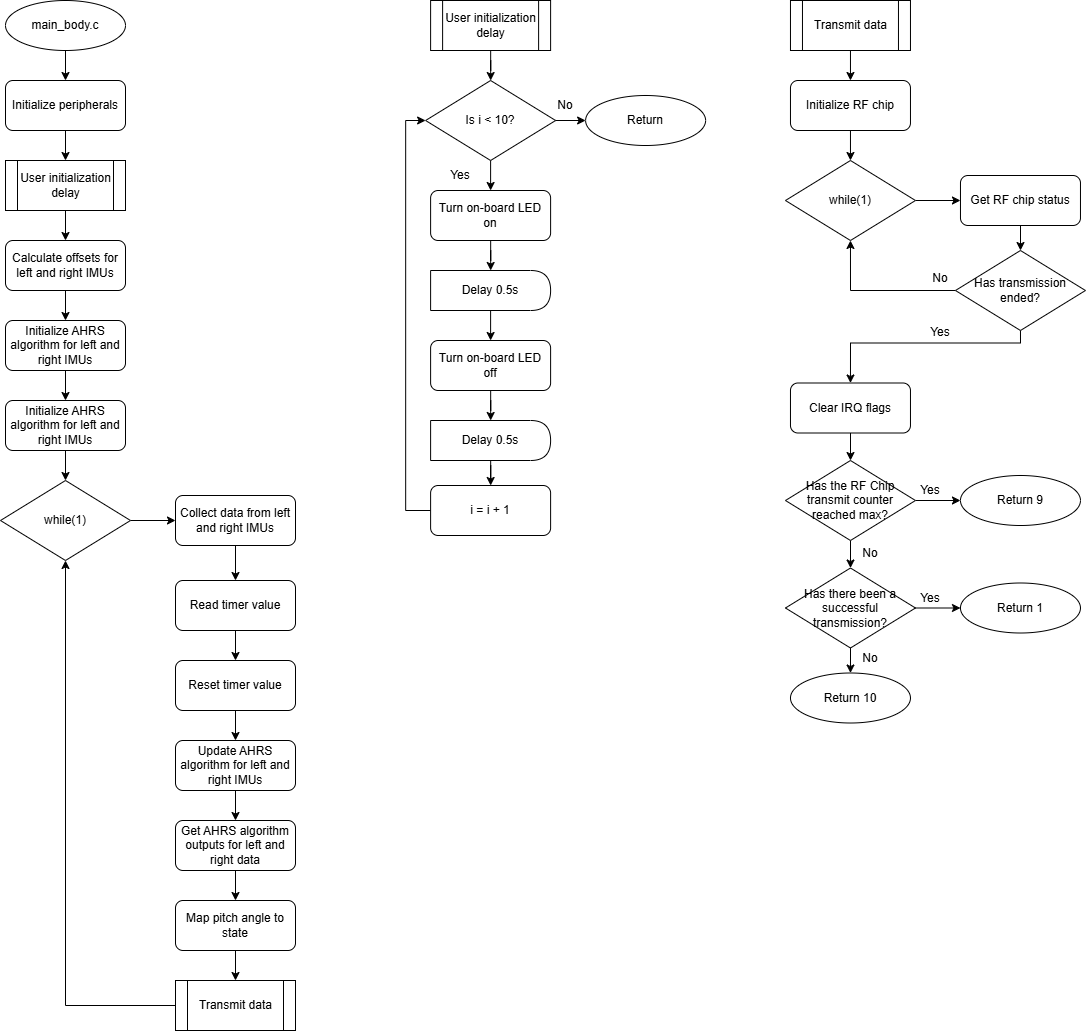
IMU data is notoriously noisy, so multiple measures were taken to reduce noise in the data. First, an initial calibration was performed for each new user. A ten second delay in the code allowed the user to move to an appropriate position (wrists horizontal) and a hundred sets of data were averaged to get an initial offset for the IMUs. Second, a sensor fusion algorithm was used to calculate orientation from IMU data. In particular, this project uses the open source Fusion library from xioTechnologies that implements the Attitude And Heading Reference System (AHRS) algorithm. A timer was used to calculate time between sample measurements for correction within the algorithm.
RF Communication
This project uses one MCU to write the collected IMU data to one nRF module as the transceiver, and then uses a second MCU to read data from the second nRF module as the receiver.
The following details the process that is needed to correctly configure and use the transciever and reciever RF modules.
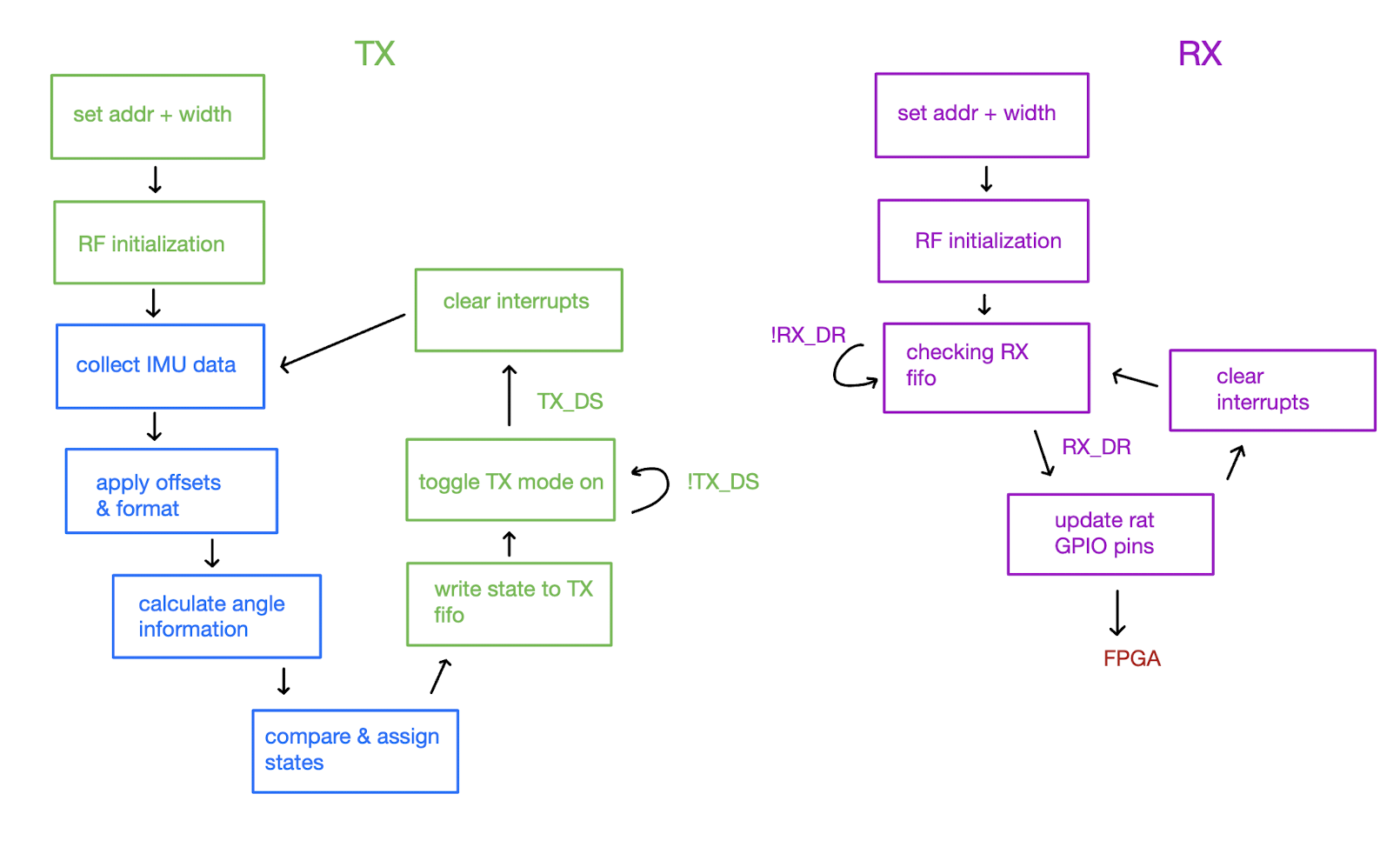
- Transmit
- Set the address/address width
- Initialize RF characteristics (rf frequency, datarate)
- Write data to TX FIFO (automatically sent out once TX mode turned on)
- Turn on TX mode by configuring mode and CS pin
- Data has been sent once TX_DS interrupt/flag is set
- Clear interrupts
- Receive
- Set address/address width
- Initialize RF characteristics
- Turn on RX mode by configuring mode and CS pin
- Wait until data is in RX FIFO
- Data has been received once RX_DR interrupt/flag is set
- Save data from RX FIFO
- Clear interrupts
This was a difficult task because none of the open source libraries we found worked for the MCU-nRF duo. To implement recieving and transcieving functionality, we adapted an existing public library.
main.c, nrf24.c, and nrf24_hal.c in the MCU code (which can be found on the Github) are the additional files that were written in addition to the SPI/RCC/GPIO files provided from MicroPs labs. nrf24.c includes all the functions needed to configure the transciever and reciever, specific to the nRF board we are using. nrf24_hal.c (hal = hardware abstraction layer) includes all the functions needed to configure the SPI send-recieve commands.
MCU Code Setup
The RF portions of the main_head.c, main_body.c, and main.c file put together the different commands from nrf24.c and nrf24_hal.c in the correct sequence for transcieving and recieving. main_head.c contains just the reciever code and only uses the RX() function. main_body.c includes the code needed to process IMU angle information and assign states, as well as the transciever code TX() to transmit said states. These can be called in main.c as needed to flash respective MCUs.
The following diagram shows a basic and high level flow of events that occur in the while loop of main for both MCUs.

The following diagram shows a more granular flow diagram of main_head.c code:

The following diagram shows a more granular flow diagram of main_body.c code: 