FPGA Design Details
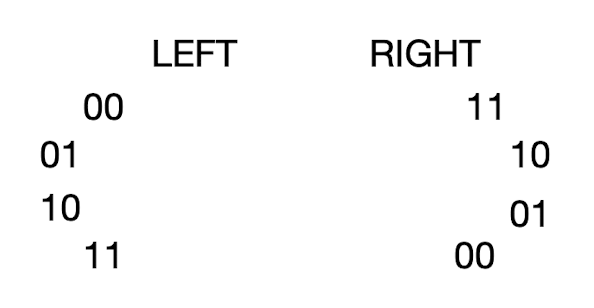
The FPGA receives state information from the second IMU through GPIO pins, and uses this information to accordingly drive PWM signals to move the motors of the rat’s arms. As explained in the documentation page, the FPGA takes input from the MCU with 4 pins such that there are 16 possible states for the motors/rat, with the first two bits representing states for the left motor and the last two bits representing the states for the right motor - for a total of 4 distinct states per motor. The FPGA drives the servo motor using PWM signal which controls the rat arm movements.
Since the PWM signals must mirror each other, the following image shows the position of the states:

A block diagram of the FPGA code setup is included below.

- Input
- Receives states from the second MCU through GPIO
- Processing
- Processes motor states received from the MCU.
- Generates PWM signals (new feature for the FPGA not covered in class or labs). (new!)
- Output
- Sends PWM signals to power servo motors via GPIO. (new!)